RO4000 | Rogers | PCB | series | laminates
Rogers PCB RO4000 series laminates
Rogers materials are by far the most popular materials for high frequency applications, high power circuits and high speed applications. In contrast to the usual FR4 material, which consists of epoxy resin and glass fiber fabric, Rogers materials are more homogeneous in the material mix and therefore more reliable in terms of signal integrity due to a significantly lower loss factor (tan d). Rogers materials are also more heat-resistant and have a significantly higher Tg. These advantages come with some disadvantages and peculiarities, which are briefly explained below. Common areas of application are telecommunications, microwave devices, 4G/5G technologies, automotive: sensors, aviation technology, military, RF technology: power amplifiers.
Material overview
This table shows the material types generally offered by Rogers with the most important properties. Please note that availability is sometimes very limited, there may be long delivery times, or the materials cannot be processed by some manufacturersm
| material | availability | main constituent | dielectric constant at 10GHz | dissipation factor (tan d) at 10GHz | thermal conductance [W/mK] |
|---|---|---|---|---|---|
| RO4003C | in stock | ceramic | 3,38 | 0,0027 | 0,71 |
| RO4350B | in stock | ceramic | 3,48 | 0,0037 | 0,69 |
| RO4360G2 | in stock | ceramic | 6,15 | 0,0038 | 0,75 |
| RO4533 | N/A | ceramic | 3,30 | 0,0025 | 0,6 |
| RO4534 | N/A | ceramic | 3,40 | 0,0027 | 0,6 |
| RO4535 | N/A | ceramic | 3,50 | 0,0037 | 0,6 |
| RO4725JXR | N/A | ceramic | 2,55 | 0,0026 | 0,38 |
| RO4730JXR | N/A | ceramic | 3,00 | 0,0027 | 0,49 |
| RO4835 | N/A | ceramic | 3,48 | 0,0037 | 0,66 |
| RO3003 | N/A | PTFE | 3,00 | 0,0010 | 0,5 |
| RO3006 | N/A | PTFE | 3,50 | 0,0015 | 0,5 |
| RO3010 | N/A | PTFE | 6,15 | 0,0020 | 0,79 |
| RO3035 | N/A | PTFE | 10,20 | 0,0022 | 0,95 |
| RO3203 | N/A | PTFE | 3,02 | 0,0016 | 0,48 |
| RO3206 | N/A | PTFE | 6,15 | 0,0027 | 0,67 |
| RO3210 | N/A | PTFE | 10,20 | 0,0027 | 0,81 |
| RT-Duroid 5870 | N/A | PTFE | 2,33 | 0,0012 | 0,22 |
| RT-Duroid 5880 | N/A | PTFE | 2,20 | 0,0009 | 0,2 |
| RT-Duroid 5880LZ | N/A | PTFE | 1,96 | 0,0019 | 0,33 |
| RT-Duroid 6002 | N/A | PTFE | 2,94 | 0,0012 | 0,6 |
| RT-Duroid 6006 | N/A | PTFE | 6,15 | 0,0027 | 0,49 |
| RT-Duroid 6010LM | N/A | PTFE | 10,20 | 0,0023 | 0,86 |
| RT-Duroid 6035HTC | N/A | PTFE | 3,50 | 0,0013 | 1,44 |
| RT-Duroid 6202 | N/A | PTFE | 2,90 | 0,0015 | 0,68 |
| RT-Duroid 6202PR | N/A | PTFE | 2,90 | 0,0020 | 0,68 |
| TMM3 | N/A | ceramic | 3,27 | 0,002 | 0,7 |
| TMM4 | N/A | ceramic | 4,50 | 0,002 | 0,7 |
| TMM6 | N/A | ceramic | 6,00 | 0,0023 | 0,72 |
| TMM10 | N/A | ceramic | 9,20 | 0,0022 | 0,76 |
| TMM10i | N/A | ceramic | 9,80 | 0,002 | 0,76 |
| TMM13i | N/A | ceramic | 12,85 | 0,0019 | |
| Ultralam 3850 | N/A | ceramic | 2,90 | 0,0025 | 0,2 |
The following prepreg grades are also available for the construction of multilayers:
| material | availability | thickness | dielectric constant at 10GHz | dissipation factor (tan d) at 10GHz | thermal conductance [W/mK] |
|---|---|---|---|---|---|
| RO4450F | on request | 101 µm | 3,52 | 0,0040 | 0,65 |
| RO4460G2 | rarely available | 101 µm | 6,15 | 0,0040 | 0,67 |
| RO4450T | rarely available | 76 µm | 3,23 | 0,0039 | 0,50 |
| RO4450T | rarely available | 101 µm | 3,35 | 0,0040 | 0,55 |
| RO4450T | rarely available | 127 µm | 3,28 | 0,0038 | 0,53 |
It should be noted here that the prepregs for multilayers only have a TG of 170°C!
Available materials
The materials listed in this table are always available from stock at LeitOn.
| material | lamination thickness | base copper (plus copper structure) | dielectric constant at 10GHz | dissipation factor (tan d) at 10GHz | TG |
|---|---|---|---|---|---|
| RO 4003 C | 0,20 | 18/18 | 3,38 | 0,0027 | 280°C |
| RO 4003 C | 0,20 | 35/35 | 3,38 | 0,0027 | 280°C |
| RO 4003 C | 0,30 | 18/18 | 3,38 | 0,0027 | 280°C |
| RO 4003 C | 0,41 | 18/18 | 3,38 | 0,0027 | 280°C |
| RO 4003 C | 0,51 | 18/18 | 3,38 | 0,0027 | 280°C |
| RO 4003 C | 0,51 | 35/35 | 3,38 | 0,0027 | 280°C |
| RO 4003 C | 0,81 | 18/18 | 3,38 | 0,0027 | 280°C |
| RO 4003 C | 0,81 | 35/35 | 3,38 | 0,0027 | 280°C |
| RO 4003 C | 1,52 | 18/18 | 3,38 | 0,0027 | 280°C |
| RO 4003 C | 1,52 | 35/35 | 3,38 | 0,0027 | 280°C |
| RO 4350 B | 0,10 | 18/18 | 3,48 | 0,0037 | 280°C |
| RO 4350 B | 0,17 | 18/18 | 3,48 | 0,0037 | 280°C |
| RO 4350 B | 0,25 | 18/18 | 3,48 | 0,0037 | 280°C |
| RO 4350 B | 0,34 | 18/18 | 3,48 | 0,0037 | 280°C |
| RO 4350 B | 0,42 | 18/18 | 3,48 | 0,0037 | 280°C |
| RO 4350 B | 0,51 | 18/18 | 3,48 | 0,0037 | 280°C |
| RO 4350 B | 0,51 | 35/35 | 3,48 | 0,0037 | 280°C |
| RO 4350 B | 0,76 | 18/18 | 3,48 | 0,0037 | 280°C |
| RO 4350 B | 0,76 | 35/35 | 3,48 | 0,0037 | 280°C |
| RO 4350 B | 1,52 | 18/18 | 3,48 | 0,0037 | 280°C |
| RO 4350 B | 1,52 | 35/35 | 3,48 | 0,0037 | 280°C |
| RO 4360G2 | 0,20 | 18/18 | 6,15 | 0,0038 | 280°C |
| RO 4360G2 | 0,31 | 18/18 | 6,15 | 0,0038 | 280°C |
| RO 4360G2 | 0,41 | 18/18 | 6,15 | 0,0038 | 280°C |
| RO 4360G2 | 0,51 | 18/18 | 6,15 | 0,0038 | 280°C |
| RO 4360G2 | 0,81 | 18/18 | 6,15 | 0,0038 | 280°C |
| RO 4360G2 | 1,52 | 18/18 | 6,15 | 0,0038 | 280°C |
UL approval
Most of the base materials mentioned above are approved in accordance with UL 94V-0. However, approval for the finished printed circuit board with Rogers material is only available for Rogers 4530B. LeitOn may only print its well-known UL number E348420 on Rogers 4350B: type "KB-06" for 1- and 2-layer PCBs, type "KB-07" for multilayers. The base material Rogers 4003C, on the other hand, is not UL-approved by Rogers itself. PCB certification of this material is therefore ruled out from the outset. This may also apply to some other materials.
Hybrid structures
The problem with prepregs of any kind is the limited shelf life in combination with minimum order quantities. This can result in either long delivery times or significant price fluctuations. A popular means of avoiding this major disadvantage is the hybrid structure. Here, the critical layers are built with a Rogers core and then pressed with widely available FR4 prepreg. The adhesion between FR4 prepreg and Rogers is also more stable than that of Rogers prepregs. When planning Rogers multilayers, the possibility of such structures should always be examined in order to save costs and time. Examples of Rogers and Rogers FR4 hybrid superstructures (schematic)
Examples of Rogers and Rogers FR4 hybrid superstructures (schematic)
2-layer - 1,6mm Rogers 4003C/4350B

1-layer - 1,6mm Rogers 4003C/4350B

4-Layer Multilayer Rogers 510 Core Laminar
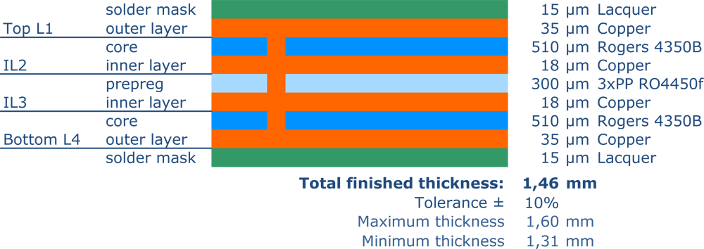
Rogers multilayer PCBs are typically manufactured using a laminate construction with outer cores, as Rogers cores exhibit very high thickness tolerances, allowing for precise impedance replication. Since there are usually only 100 µm prepregs available, which can be stacked in limited numbers (2–4 layers), the total thickness is somewhat restricted in this configuration.
3-Layer Multilayer Rogers 510 Core Laminar

The manufacturing process for 3-layer Rogers PCBs is identical to that of 4-layer boards, except that one layer is completely etched away.
4-Layer Hybrid - 1,5mm Rogers 4003C filled Core
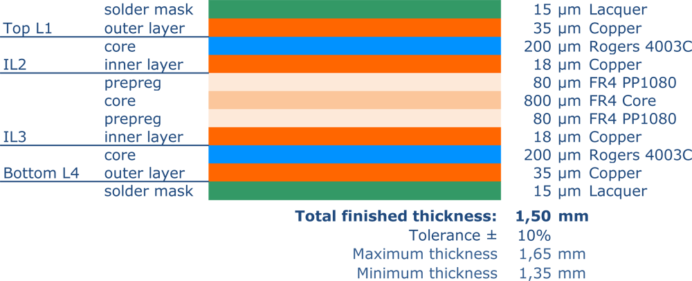
The most common Rogers cores used in multilayers are in the range of 200–250 µm. Since prepregs can only be stacked in limited numbers, filler cores are used to achieve specific final thicknesses. This configuration can also be supplied with just one Rogers core.
4-Layer Hybrid 1 Rogers 4350B Core
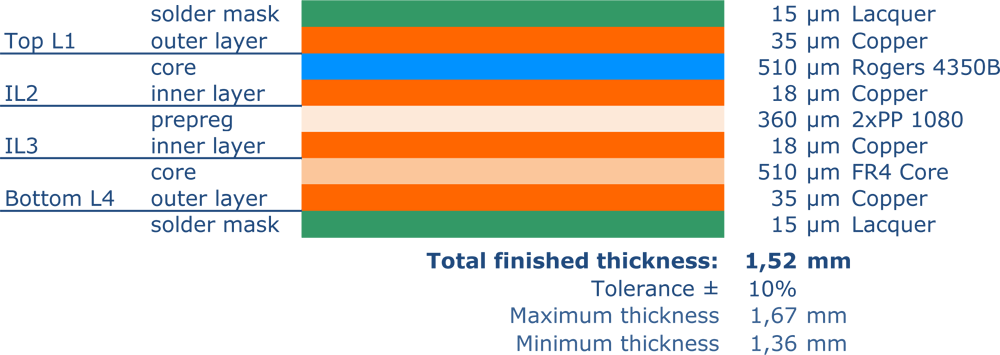
As impedance-controlled traces often run on only one outer layer, non-HF-relevant areas can be implemented in FR4, significantly reducing costs. This configuration can also be manufactured with two outer Rogers cores.
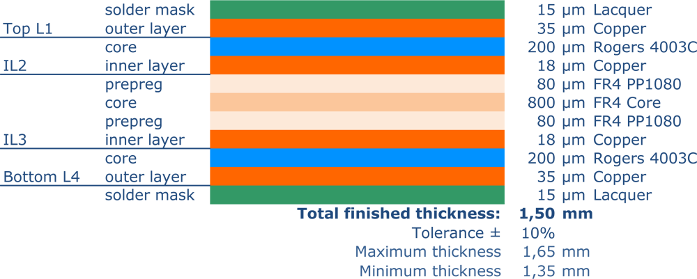
4-Layer Hybrid 2 Rogers 4003C Core + filled core FR4
12 Layer Hybrid - 1,63 mm FR4/Rogers 4350B
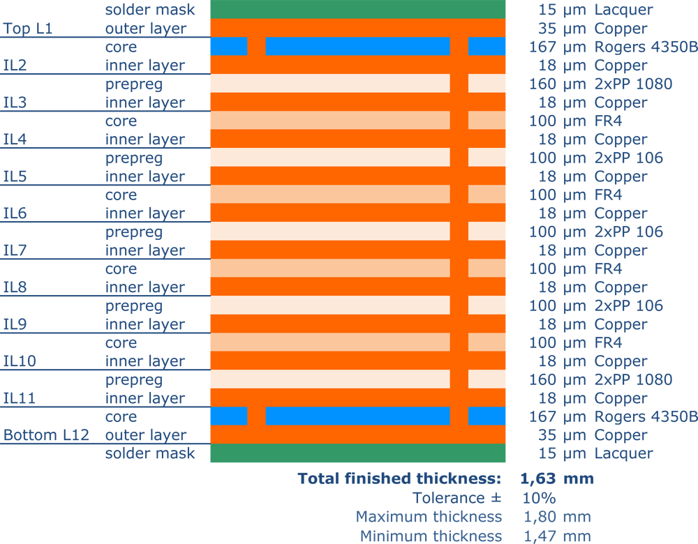
Hybrid technology is not limited to a specific number of layers and can be designed, as in this example, with up to 12 layers. Additional layers can optionally be implemented in Rogers material, or blind/buried vias can be used.
12-Layer Multilayer Rogers - 1,7mm Half-Stack
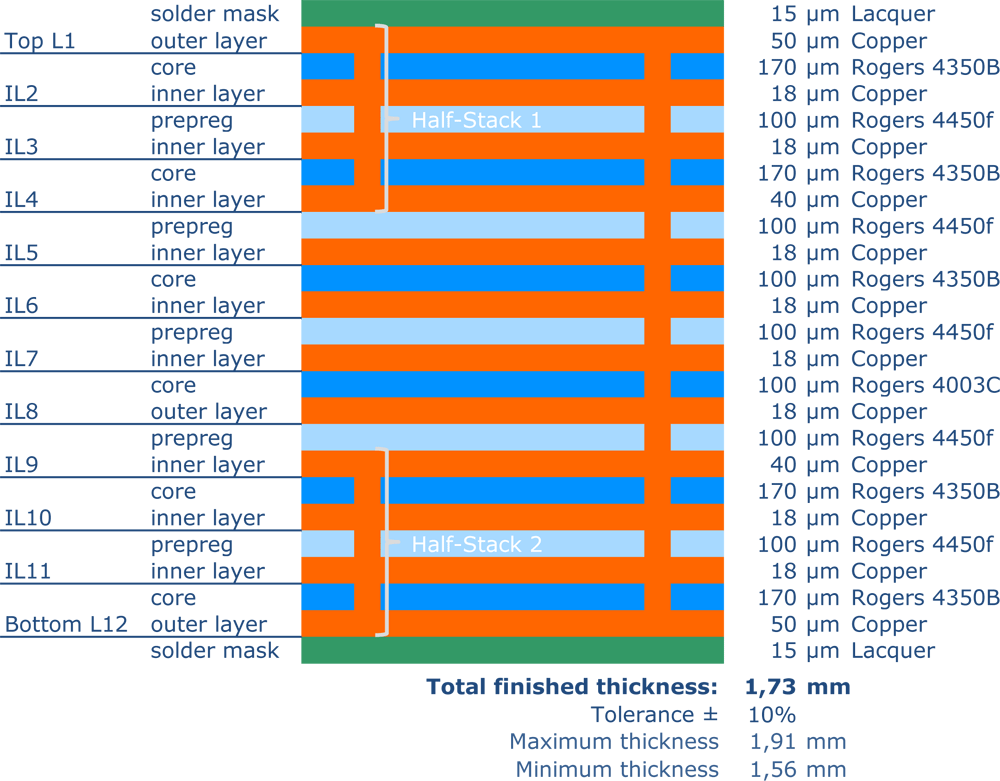
HF boards can also be produced in high layer counts as pure Rogers designs and combined with additional HDI technologies. One example is the half-stack technology. Feel free to contact our technical sales team if you have any questions or specific requirements.
Production restrictions RO4000 series
As mentioned in detail, HF materials also have some disadvantages when it comes to processing. For example, very thin ceramic materials are extremely brittle. This property means that even thicker material thicknesses should not be scribed, for example, as these scribes break completely very quickly. Furthermore, Rogers materials usually have a lower copper adhesion due to their very smooth surface. In extreme cases, this means that very thin conductor runs barely hold or break off under even low mechanical loads. For this reason, plugging and filling processes, in which the printed circuit board must subsequently be ground (structures can detach from the board), are only available to a limited extent.
Summary:
- Material breaks more easily
- No scoring
- Poorer copper adhesion of structures
- Limited filling or plugging of holes
- Not well suited for edge metallization
- Longer milling times, high tool wear, short tool life
Tips
If high frequencies are actually running on the PCBs, we always recommend ordering an impedance measurement. There are also surfaces that can interfere with such impedances. The widely used HAL lead-free is unpopular due to its lack of planarity. Electroless nickel-gold, on the other hand, has a reputation for having a negative impact on signal integrity due to its porous nickel layer. In such critical areas, we can offer nickel-free chemical gold. Please ask for this explicitly, as it is not a standard. Normal electroless nickel-gold (ENIG) or nickel-palladium-Gold (ENEPIG) are common at Rogers.


